
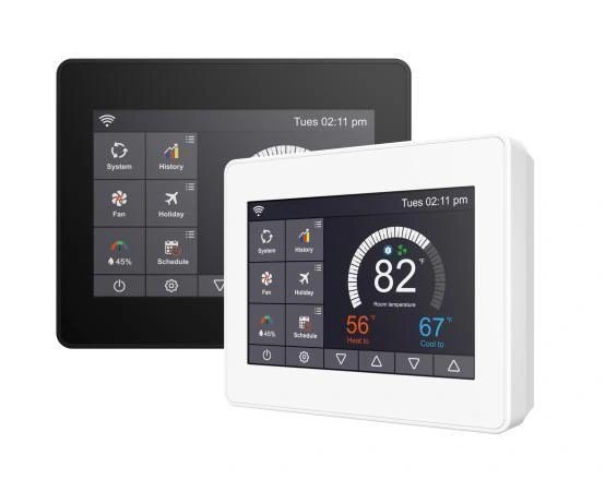
FM10FU
Smart WiFi Heat Pump Thermostat (3H/2C)
A configurable interface for staged heating and cooling, including compatible heat pump and conventional systems.
View product →RESIDENTIAL · HEATING & COOLING
Configure room control around your equipment stages, reversing valve and auxiliary heat.
SYSTEM OVERVIEW
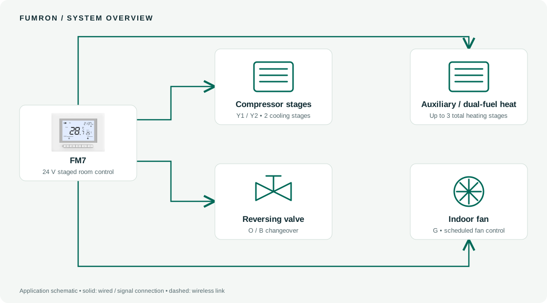
A selected heat-pump thermostat calls for the required heating or cooling stages. System configuration must match the equipment type, reversing-valve logic and auxiliary heating sequence.
SYSTEM COMPONENTS
SPECIFICATION CHECKLIST
COMPATIBLE CONFIGURATIONS
Products below are alternatives or complementary components, not a pre-validated kit. Choose the exact electrical and communication variants for the project.
A configurable interface for staged heating and cooling, including compatible heat pump and conventional systems.
View product →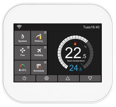
A configurable interface for staged heating and cooling, including compatible heat pump and conventional systems.
View product →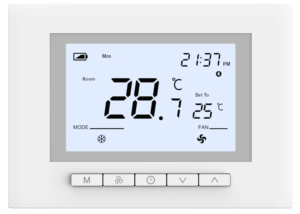
A clear LCD room interface for up to 3H/2C heat-pump or dual-fuel systems, and 2H/2C conventional heating and cooling.
View product →